Wind Turbine
Designer for Miniature Wind Turbine
Skills: Solidworks, FEA, 3D Printing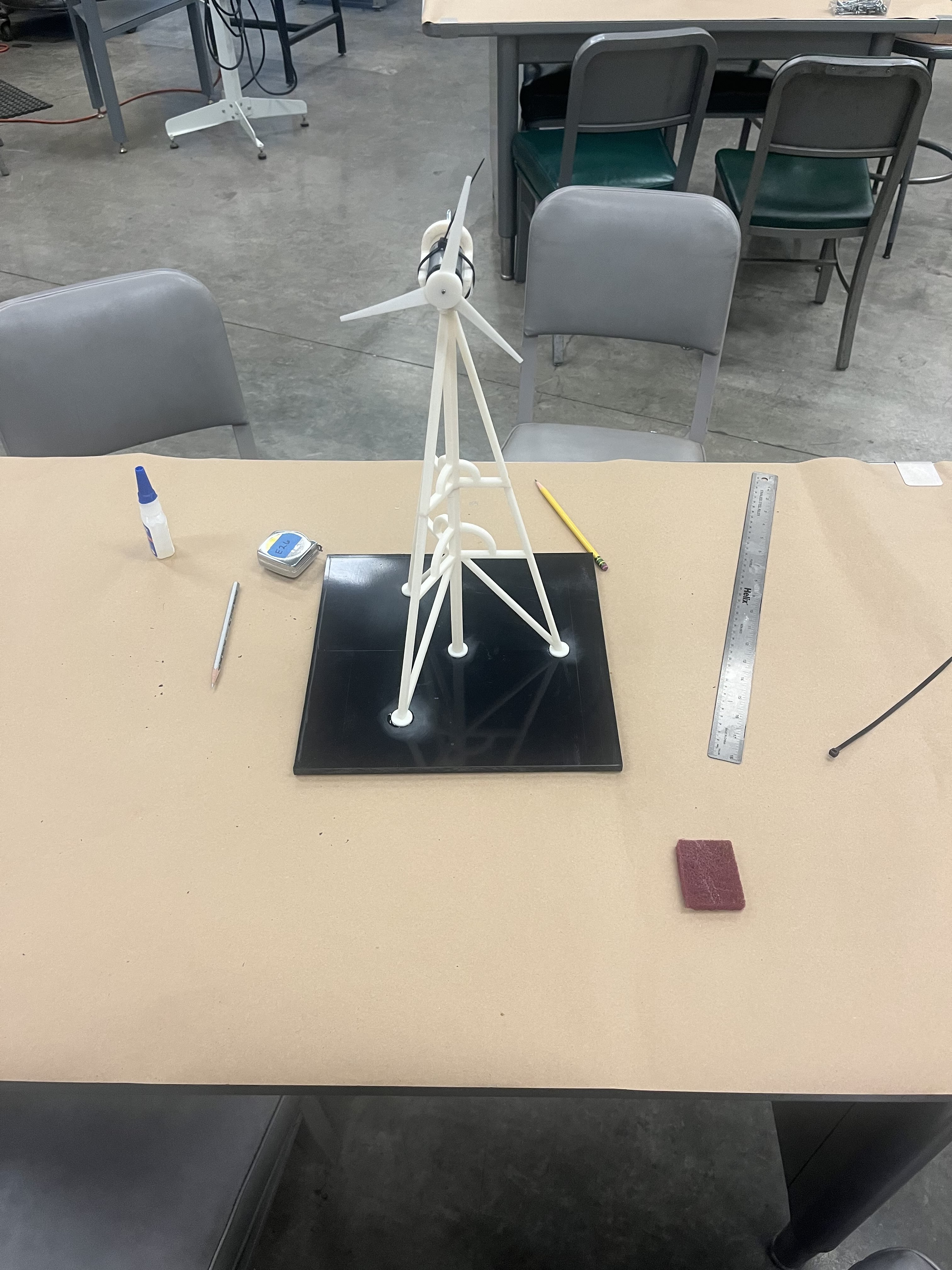
Project Overview
This was a project for my three-dimensional modeling for design course (ENGIN26). We were tasked to create a miniature wind turbine that could generate power. We designed the towerss as well as the airfoil design.
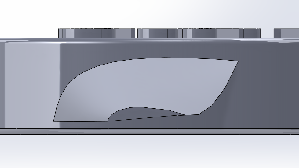
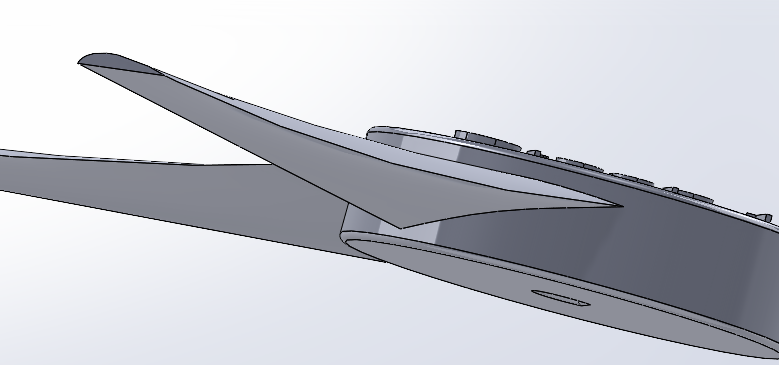
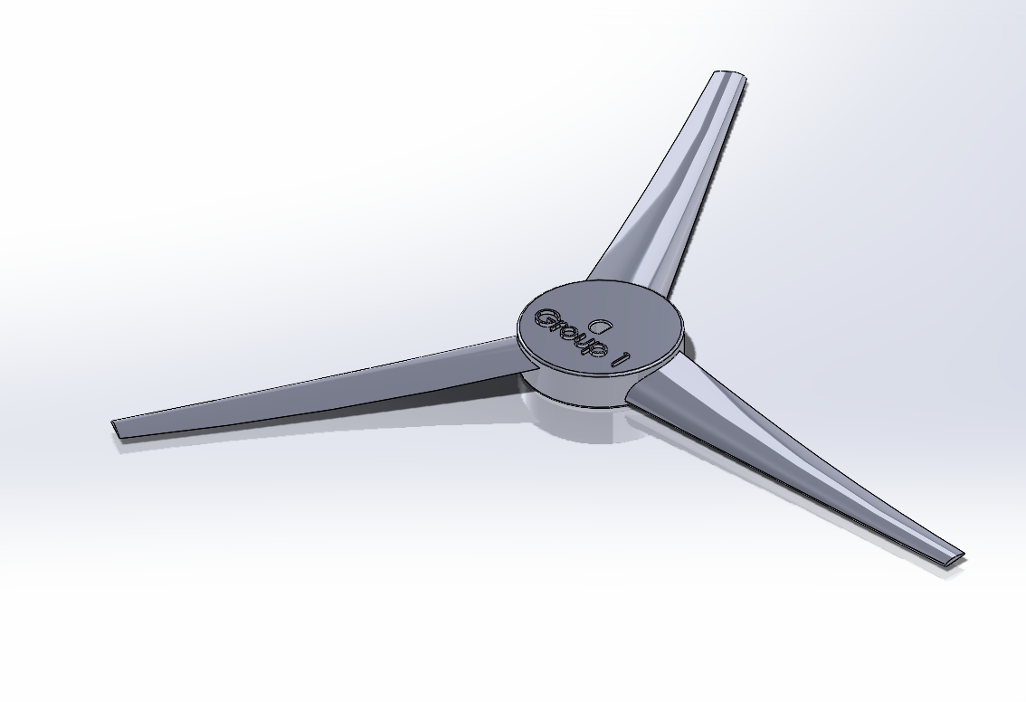
Blade Design
As a team, we chose an angle of twist of 20° to optimize aerodynamic efficiency. Our blade profile features a curved top and flat bottom, streategically designed to generate lift, while maintaining a slender profile compared to designs we had seen. Our blade length was 3 inches long, whihch was the maximum length allowed to capture wind and generate lift.
Tower Design
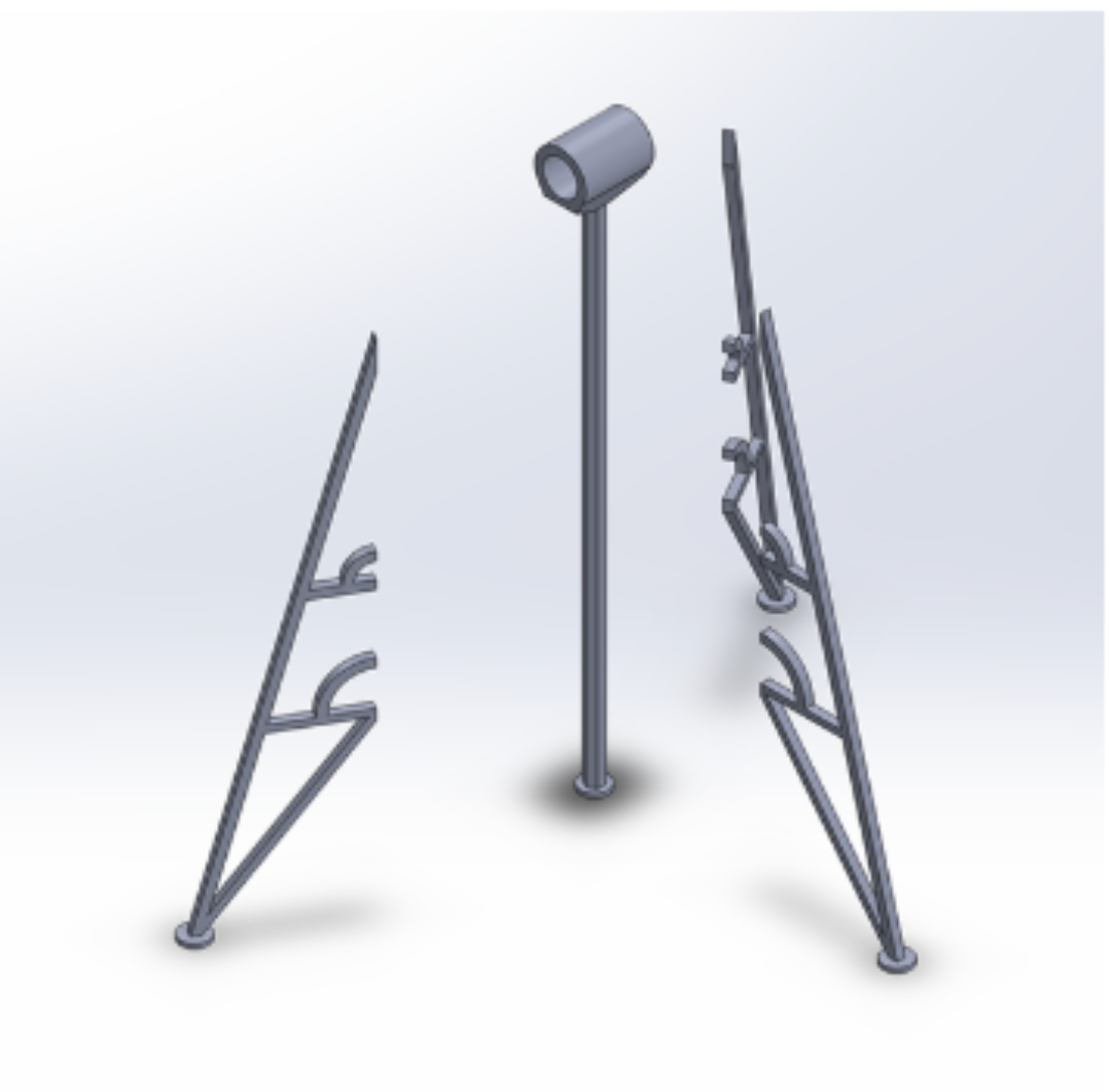
We divided our tower structure into two sections for 3D printing and later fused them together. The tower's design features a triangular base for stability and resilience against wind, with radial symmetry ensuring structural integrity. We opted for a truss structure similar to real-world wind turbines to enhance stability and cost efficiency. Round supports between the middle pillar and horizontal supports were used to improve load-bearing capacity by evenly distributing compression and tension forces. Thin circular base plates were also added to the triangular base to increase surface area and simplify the gluing process.
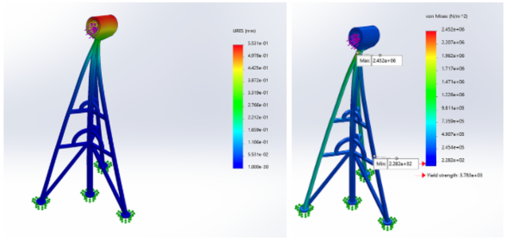
Using FEA, the highest displacement we had was 0.5531 mm, meaning that the top of our motor mount (the region affected), would move that much under a 1kg load. We also tested stress on the von mises criterion, which tests yield strength. We found that the yield trength of our model was 3.783 N/m2.
Mechanical Testing
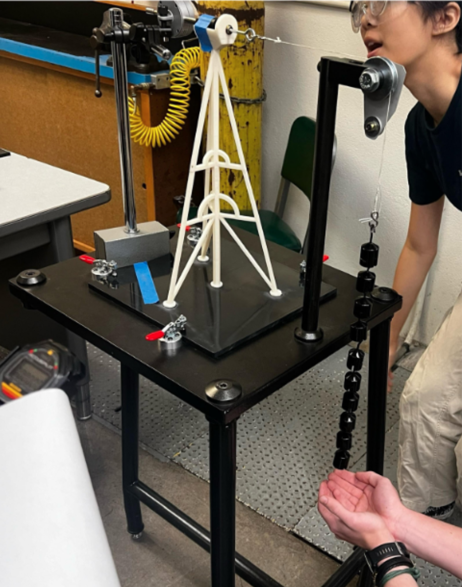
The testing setup included a vertically mounted pulley positioned about 16 inches above the table surface. Next to the pulley, a vertical mount held a dial indicator to detect small deflections.
An eyebolt was threaded into the rear hold of the motor housing to attach a tensioned string for tower bending. The tower, without the motor or blade, was clamped to the table, aligned with the pulley
to apply normal force when tensioned. The string was connected to the eyebolt and threaded over the pulley.
We incrementally applied 100-gram weights to the string, increasing tension gradually. After each weight was added, we recorded deflection measurements from 0 to 1kg, along with visual observations. At a load of
9.81N, we had a displacement of 1mm. We had the lowest mass out of all project teams, and had the highest strength to weight ratio.
Using FEA, the highest displacement we had was 0.5531 mm, meaning that the top of our motor mount (the region affected), would move that much under a 1kg load. We also tested stress on the von mises criterion, which tests yield strength. We found that the yield trength of our model was 3.783 N/m2.
Power Generation Testing
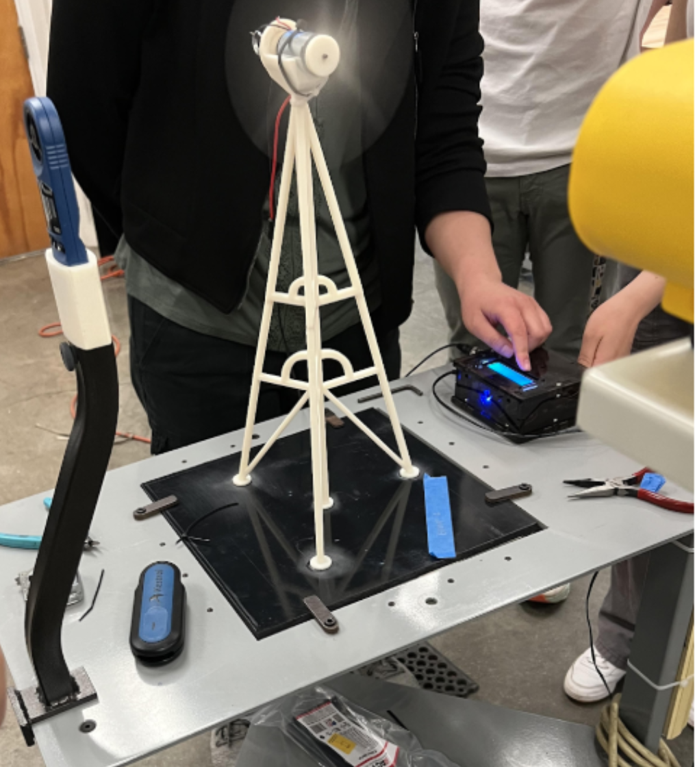
In our experimental setup, we directed a wind blower at the turbine, ensuring that the wind entered the blades at a consistent speed of around 25 mph.
An electrical meter was integrated into the circuit, placed in series with the motor to measure key electrical parameters: voltage (V), current (mA), and power (mW).
To fine-tune the turbine's performance, a load box was incorporated into the circuit, allowing us to adjust the loading conditions by varying the resistance.
To measure the blade's rotational speed (rpm), we employed a tachometer. A small piece of reflective duct tape was adhered to one of the turbine blades to serve as a marker.
This marker enabled the tachometer to detect each complete revolution of the blade. The tachometer was strategically placed next to the blower, ensuring continuous and accurate
speed readings throughout the experiment.
We began by turning off the blower and resetting the potentiometers, effectively reducing the circuit's resistance to its minimum level. This step was essential to establish a
baseline for the turbine's operation under minimal load. Once the setup was prepared, we activated the blower, allowing wind to flow through the blades, and initiated the rotation.
As the turbine blades began to spin, we carefully adjusted the loading conditions by fine-tuning the potentiometers. By increasing the circuit resistance gradually, we could
simulate different operational conditions and observe how these adjustments impacted the turbine's performance.
Our power generation was not the greatest due to poor blade design. Our peak power generation was 320 mWatts at 2.2 Volts and 140 mAmps. Our highest blade RPM was 4600.