ME100 Final Project — Smart Electric Skateboard System
Skills: ESP32, MicroPython, ESP-NOW, 3D Printing, OnShape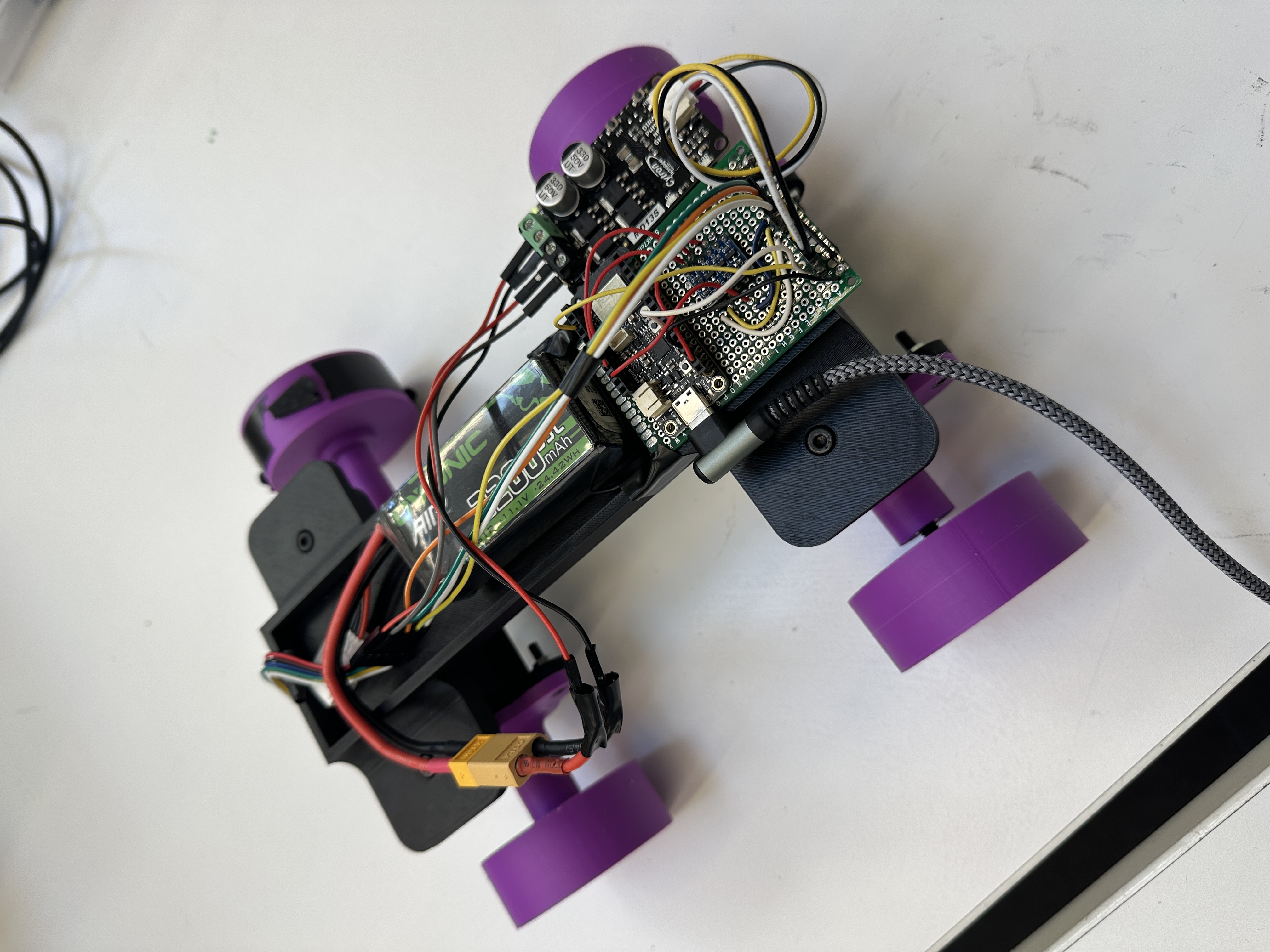
Project Overview
This was a final project for ME100 (Design of Electromechanical Systems), completed in collaboration with teammates Roshni Arun and Jade Stashin. We designed and built ICBreadboards — a smart electric skateboard system aimed at enhancing rider safety, preventing theft, and restoring the engagement of traditional skateboarding.
Our three core objectives were:
1. Design a push-controlled acceleration system so riders can propel the board naturally, without relying solely on a remote
2. Implement an ultrasonic-based foot-braking detection system for intuitive, safe deceleration
3. Build a wireless anti-theft alarm system that triggers when unauthorized motion is detected on an armed board
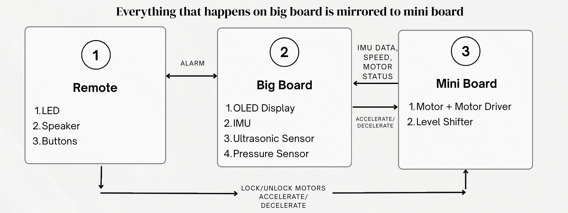
The system used three ESP32 microcontrollers communicating over ESP-NOW: a Big Board (sensing + feedback), a Mini Board (motor control), and a handheld Remote. I was responsible for the code architecture, ESP-NOW communication protocol, sensor integration, and PCB design for the remote.
Big Board — Sensing & Feedback
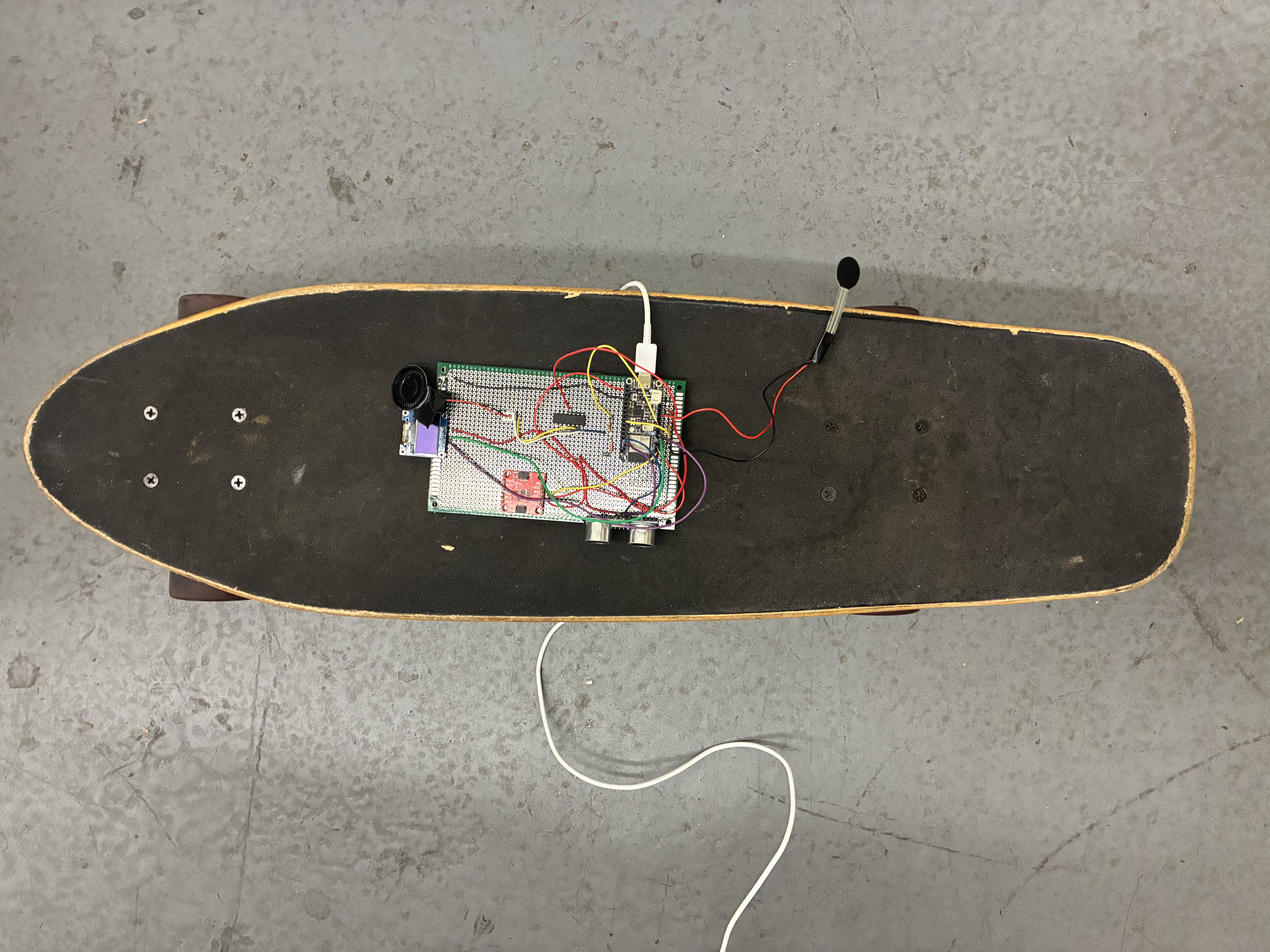
The Big Board served as the brain of the system, integrating an IMU, FSR pressure sensor, and ultrasonic distance sensor with an ESP32 microcontroller. An OLED display provided real-time telemetry — showing speed, acceleration, obstacle detection status, and whether the board was armed or disarmed.
The IMU detected push-off acceleration to trigger motor speed increases, while also powering the anti-theft system by detecting unauthorized movement when locked. The pressure sensor ensured acceleration only engaged when a rider's foot was properly placed. The ultrasonic sensor handled foot-cued braking by detecting when a rider dragged their rear foot near the board.
All sensor data was processed on the Big Board and wirelessly relayed to the Mini Board via ESP-NOW for real-time motor execution.
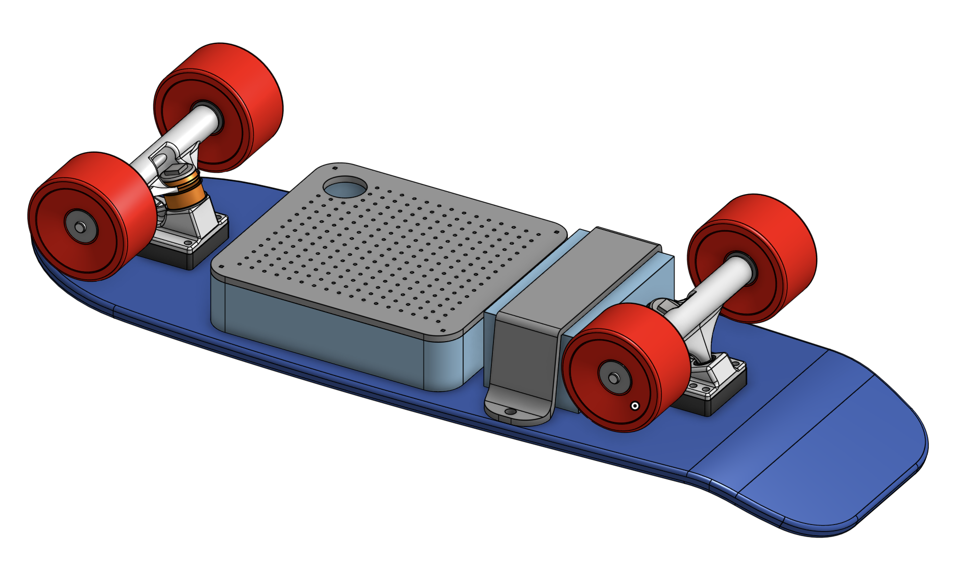
Big Board CAD
Originally, we intended to prototype a full working version of the skateboard. However, due to high-voltage safety constraints and challenges getting the larger system operational within the timeline, we validated our approach using a miniature model. We separated big board control to a smaller miniature model that would replicate the motion for safety.
Mini Board — Motor Control
The Mini Board acted as the dedicated motor controller, receiving wireless commands from both the Big Board and Remote to drive a 12V DC motor via an H-bridge driver. Motor speed was controlled through a PWM signal (1kHz, 0–1023 duty cycle), with Hall effect sensors providing position feedback through a level shifter to accommodate 5V–to–3.3V logic conversion.
The control logic included incremental acceleration (2% steps), automatic deceleration when obstacles were detected (5% reduction every 0.5 seconds), and safety interlocks that prevented motor operation when the board was armed or an obstacle was present. The motor was powered by an isolated 11.1V LiPo battery separate from the ESP32 logic supply.
Remote & PCB Design
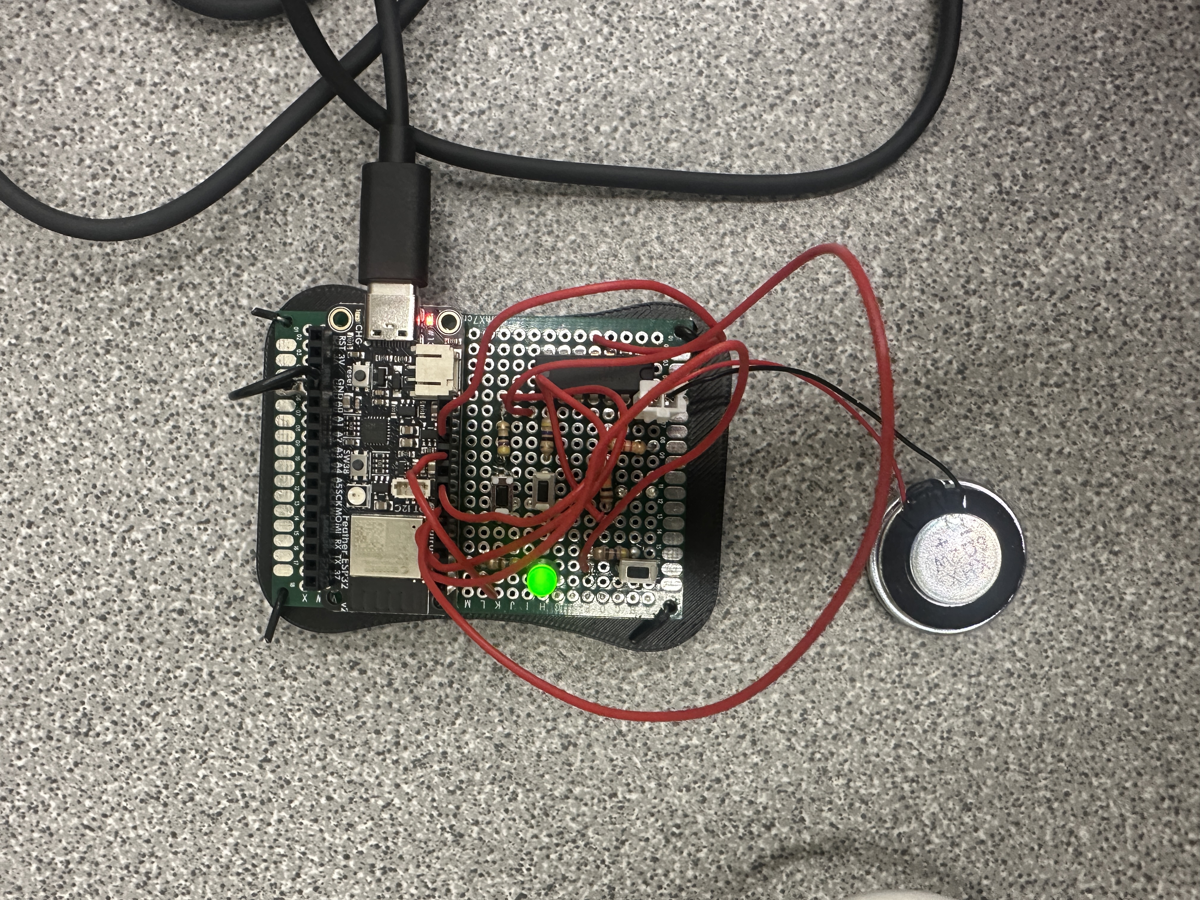
The handheld remote used an ESP32 Feather with three buttons for acceleration, deceleration, and security mode toggling. A status LED indicated armed/disarmed state, and a PWM-driven speaker provided audio feedback for button presses and theft alarms. When the board detected unauthorized motion while armed, the remote received an "ALARM" signal and triggered a sustained high-frequency alert in sync with the board's onboard speaker.
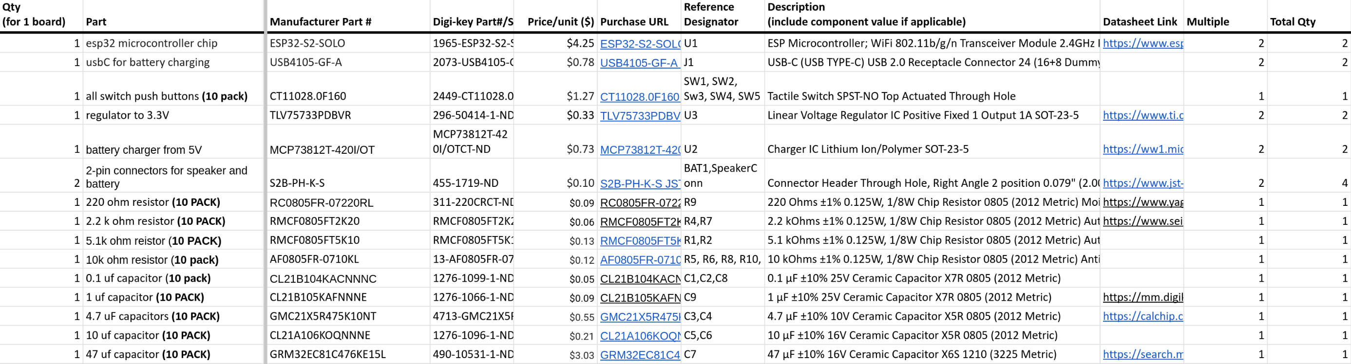
Beyond the perfboard prototype, we also designed a custom PCB in KiCAD using an ESP32-S2-SOLO chip. The PCB matched all remote capabilities with a more compact, polished layout — battery-powered and rechargeable via USB-C, with a buck regulator stepping down to 3.3V logic. Test points and mounting holes were added for debugging and physical integration.
Manufacturing & CAD
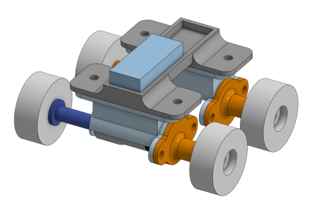
The mechanical components were designed in OnShape and 3D printed on a Bambu P1S using PLA filament at 5% infill, balancing structural integrity with material efficiency. Motor mounts, wheel housings, and structural supports were all custom-designed. Wheels were fastened using M6 heat-set inserts and Torx-head shoulder bolts for precise alignment under load, with remaining assembly using M4 hardware for ease of maintenance.
The 12V DC motor's keyed shaft was coupled to a custom friction-fit flange for efficient torque transmission. All electronic components were hand-soldered onto perf boards for reliable signal routing and power distribution.
Exploded Assembly View
The exploded CAD view reveals how each subsystem fits together — the deck platform, motor sub-assembly with flanged shaft coupling, truck housings, and wheel attachments all designed for straightforward assembly and access during prototyping. Each part was designed to be independently removable so electronics and mechanical components could be iterated without full disassembly.
Code Architecture & Communication
All three ESP32s communicated over the ESP-NOW wireless protocol using defined message signals — covering acceleration, deceleration, obstacle detection, arming/disarming, and alarm triggering. The full system was written in MicroPython using the Thonny IDE.
Key signals included push-based acceleration from the Big Board's IMU, manual override from the Remote, automatic obstacle deceleration, and the anti-theft ALARM/LOCK/UNLOCK handshake between all three boards. The modular signal table ensured clean separation of concerns across boards while maintaining real-time responsiveness.
Working Prototype Videos
Big board push-controlled acceleration
Remote control driving the small board end-to-end
Anti-theft alarm system