Excavate
View ReportME130 Final Project — 6-Bar Scoop-and-Dump Excavation Mechanism
Skills: SolidWorks, Graphical Synthesis, Kinematic Analysis, Python, Laser Cutting, 3D Printing, Machining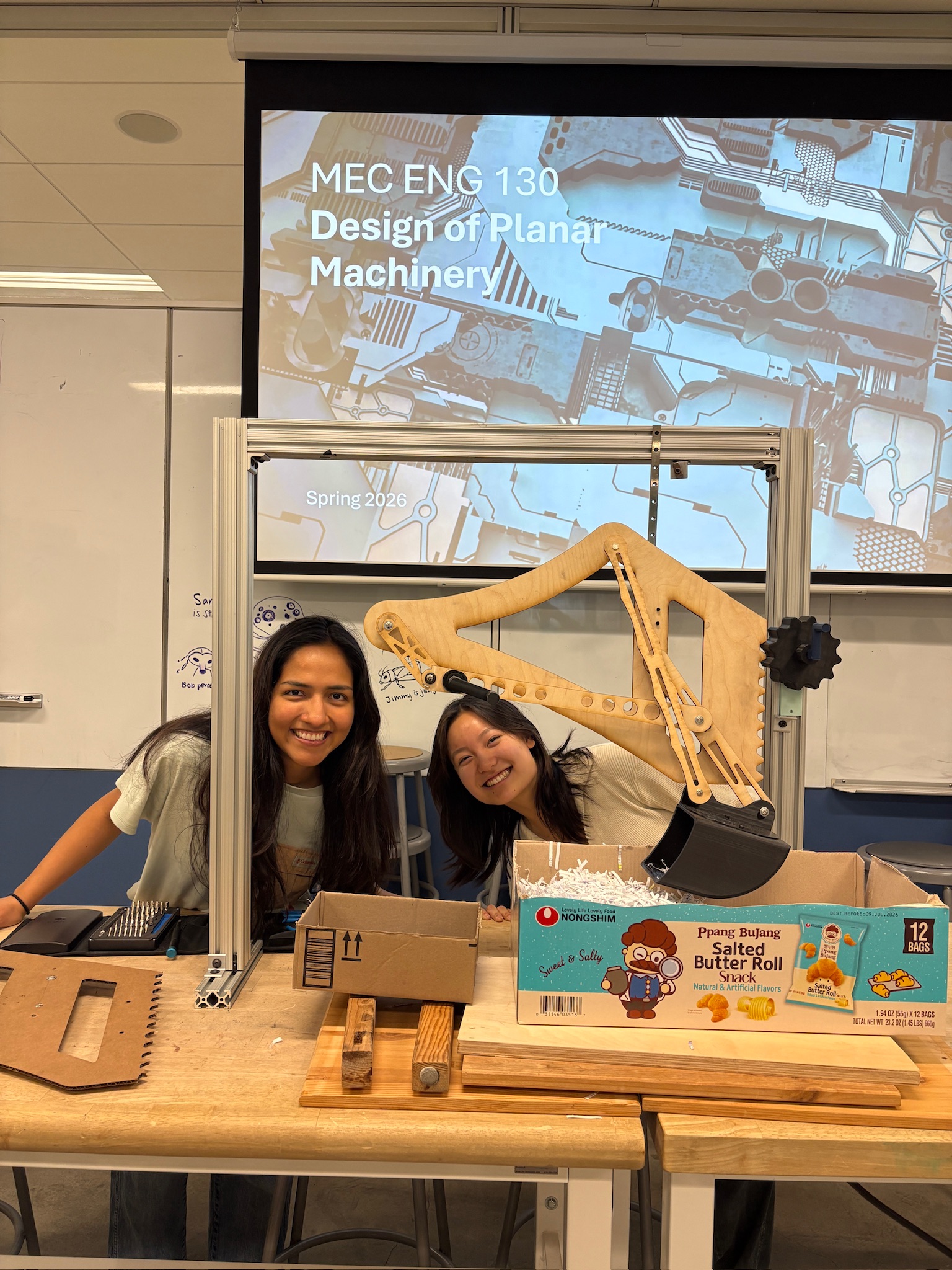
Project Overview
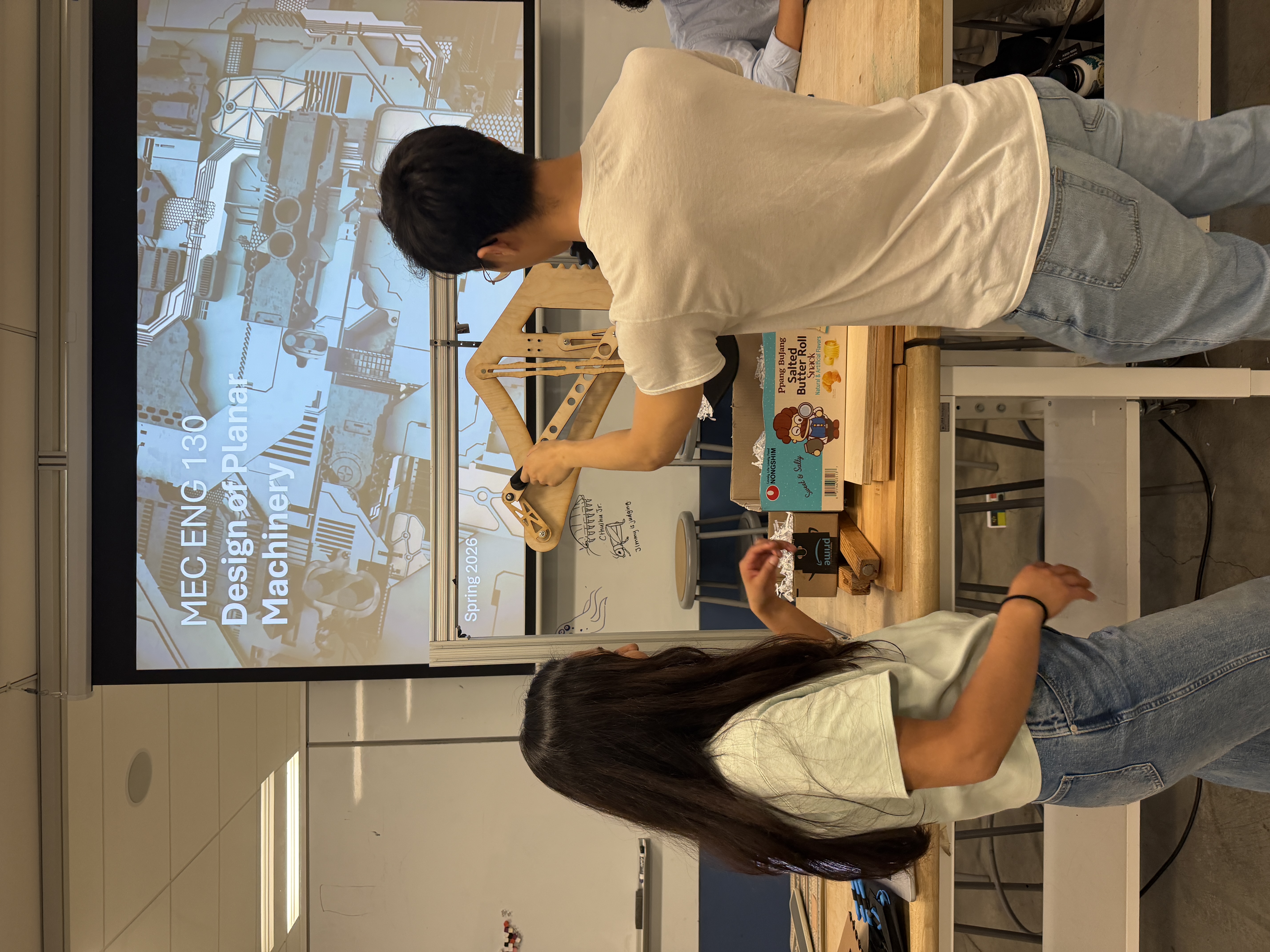
Excavate is a 6-bar scoop-and-dump excavation mechanism designed for ME130 (Kinematics and Dynamics of Machines), in collaboration with Diana Bolaños. The goal was to design and build a mechanism that allows a user to continuously drive a crank with one hand while raising and lowering the system vertically with the other using a rack-and-pinion.
The design had to satisfy several hard constraints: the scoop needed to move smoothly through the critical scoop-and-dump positions without any linkage rearrangement, all linkage lengths had to fit within an existing 8020 aluminum frame, and every part had to be manufacturable on the Jacobs Makerspace laser cutter or the Bambu H2C 3D print bed.
The final prototype achieves a prescribed scooping motion from a hand crank, with vertical adjustment via a rack-and-pinion system. Linkages were laser cut from 0.25" plywood, the scoop and handles were 3D printed in PLA, and the frame was assembled from aluminum 8020 extrusions from the Co-Design Lab.
Design Methods — Graphical Synthesis
We used three-position graphical synthesis to design the initial four-bar linkage, defining poses for the start of scooping, end of scooping, and the final dump position. Key free choices were scoop orientation at each pose and the spacing between poses.
After synthesis, we checked the Grashof condition. Since S+L > P+Q (18.726 > 17.568), the four-bar is a Class II non-Grashof rocker-rocker with no fully rotatable links. To enable continuous crank input, we added a dyad to complete the six-bar mechanism. We then used graphical dyad synthesis to place the input pivot.
Rather than applying the method of inversion for further tuning, we refined geometry through CAD iteration. A key finding: when coupler points were closer to collinear, synthesized fixed pivots moved farther apart. Using poses with more angular and positional variation produced more compact pivot locations and shorter linkage lengths — critical for fitting within the frame.
CAD Iterations
Multiple CAD iterations were produced during the graphical synthesis process, each testing different coupler pose choices and pivot placements. Early iterations with nearly collinear coupler points resulted in pivot locations too far apart to fit the frame. Iterating toward poses with greater angular separation converged on a compact geometry that satisfied all dimensional constraints.
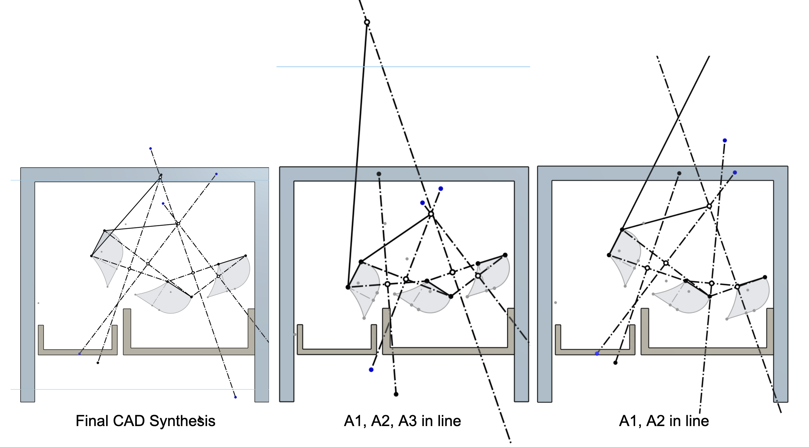
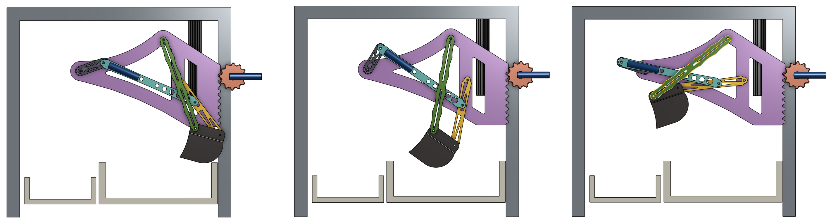
Three critical scoop poses: initial scooping, end of scooping, and dump
Final Linkage Geometry
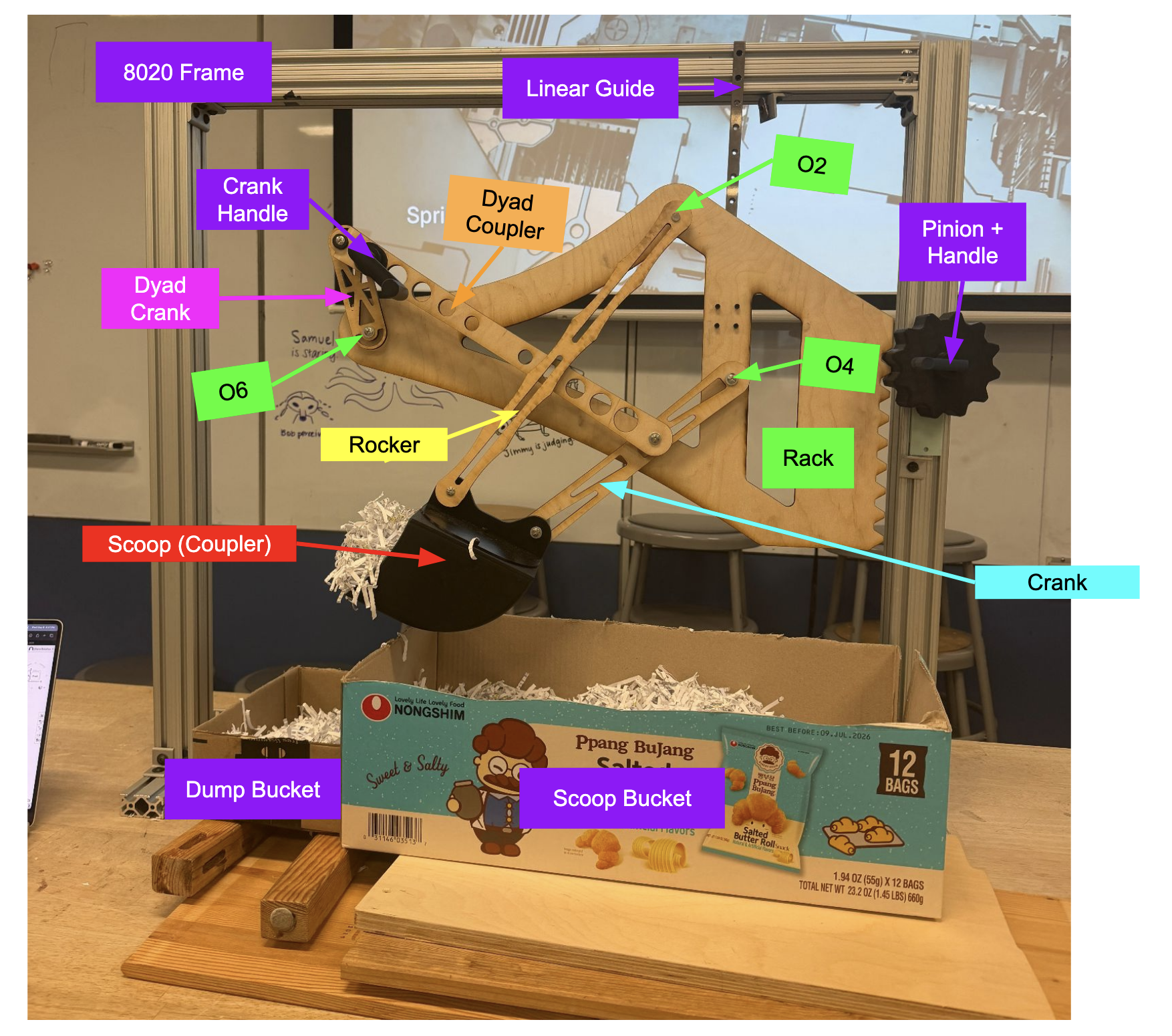
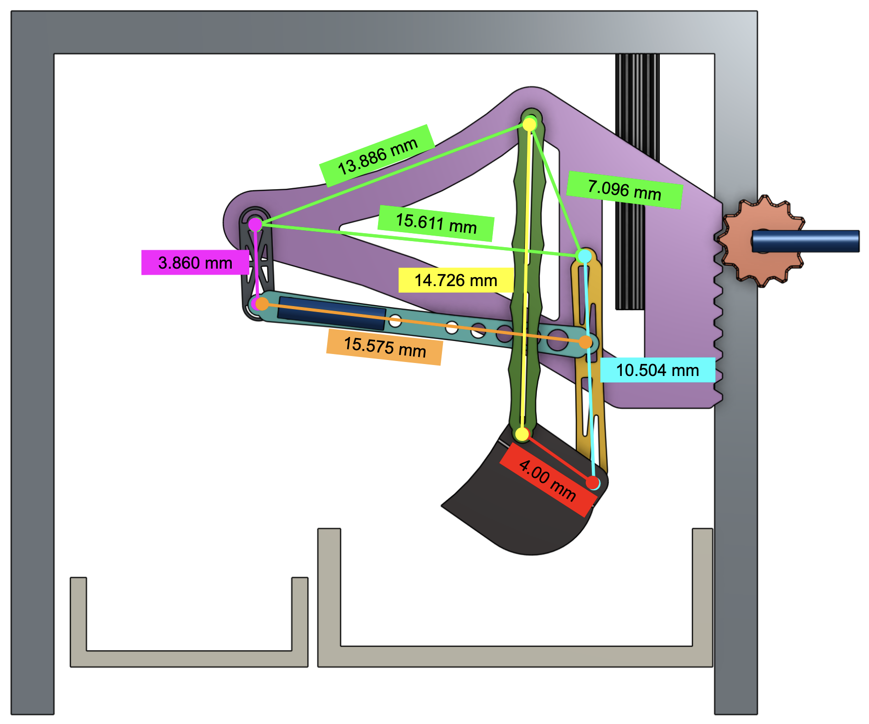
The final six-bar mechanism used the following link lengths and fixed pivot distances, all determined through graphical synthesis and refined in CAD:
Dyad crank: 3.856 mm | Dyad coupler: 15.575 mm | Rocker: 10.472 mm | Crank: 14.726 mm | Coupler (scoop): 4.000 mm
Ground link O₂O₄: 7.096 mm | O₆O₂: 13.886 mm | O₄O₆: 15.611 mm | O₆O₄: 6.148 mm
Speed holes were added to all plywood links after initial synthesis to reduce weight and improve laser-cut manufacturability, while keeping the cross-sections structurally sound under the expected prototype loads.
Kinematic Analysis — Vector Loop Method
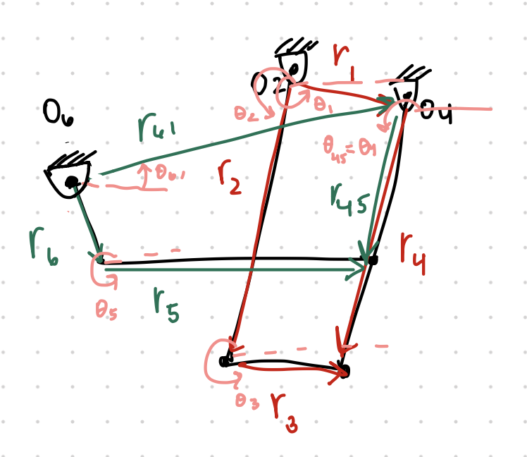
Position, velocity, and angular acceleration analyses were performed using the vector loop equations derived from the six-bar geometry. The two loop equations are:
Loop 1: r₁ + r₄ = r₂ + r₃ Loop 2: r₆ + r₅ = r₆₁ + r₄₅
Each was decomposed into real and imaginary components, then solved analytically in Python. The code sweeps the input angle θ₆ through a full rotation, solving each link's position, then uses those results to compute angular velocities and angular accelerations assuming a constant input of ω₆ = 1.0 rad/s and zero input angular acceleration.
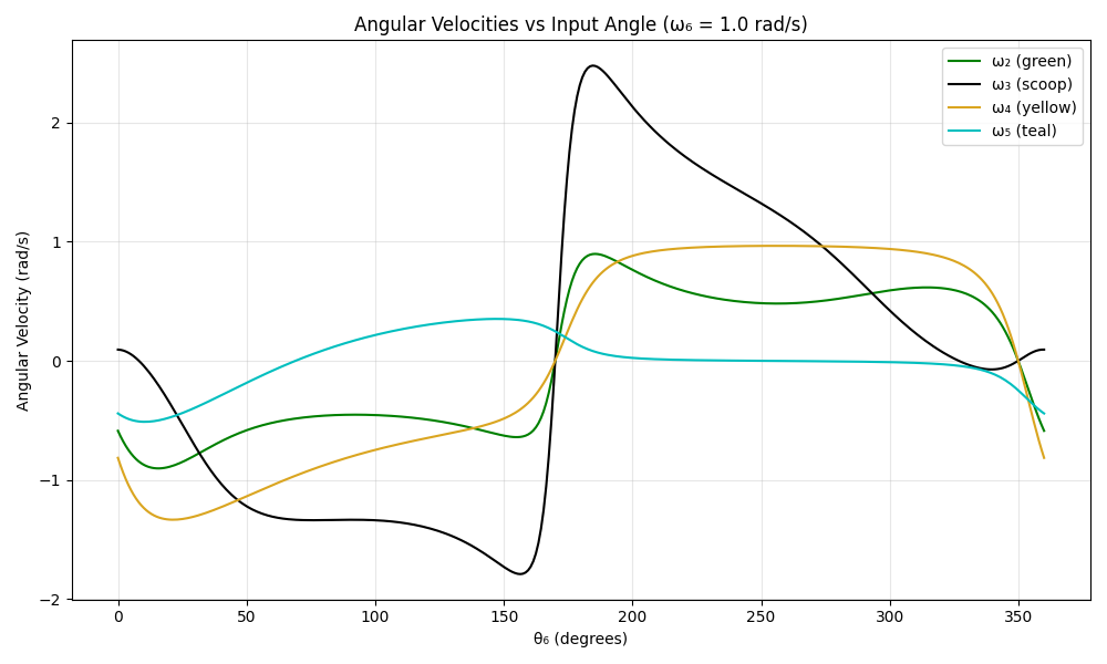
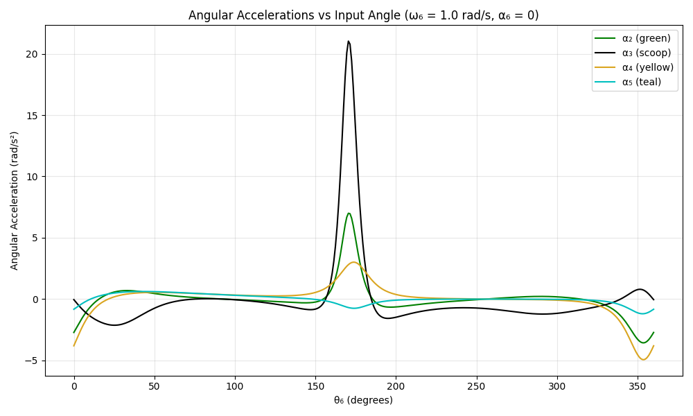
The angular velocity plot shows that the scoop link does not rotate at a constant rate even with constant crank input — expected behavior for a six-bar linkage. This natural variation means the scoop moves slower during collection and faster during dumping, which is desirable for excavation tasks. The angular acceleration plot shows the corresponding variation over one full input rotation, confirming smooth, continuous motion throughout the cycle.
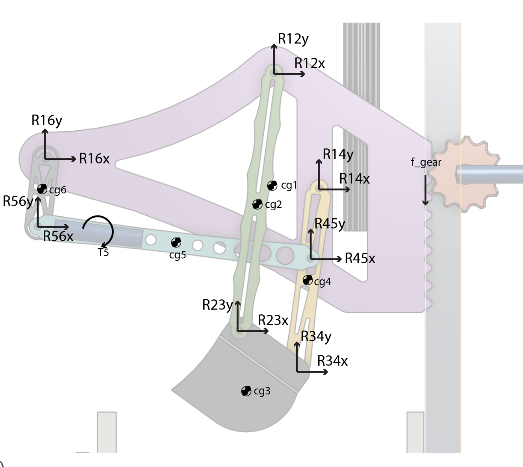
Static Force Analysis
A static force analysis was performed at the initial scooping position, where the scoop experiences the highest resistance from the medium. Free body diagrams were drawn for each link and the resulting pin forces were solved analytically.
The analysis estimated relative joint loading across the mechanism and confirmed that the selected hardware and plywood linkages were appropriate for prototype-level loads. As expected, the highest forces concentrated near the scoop and the adjacent transmission links, which directly resist the scooping load.
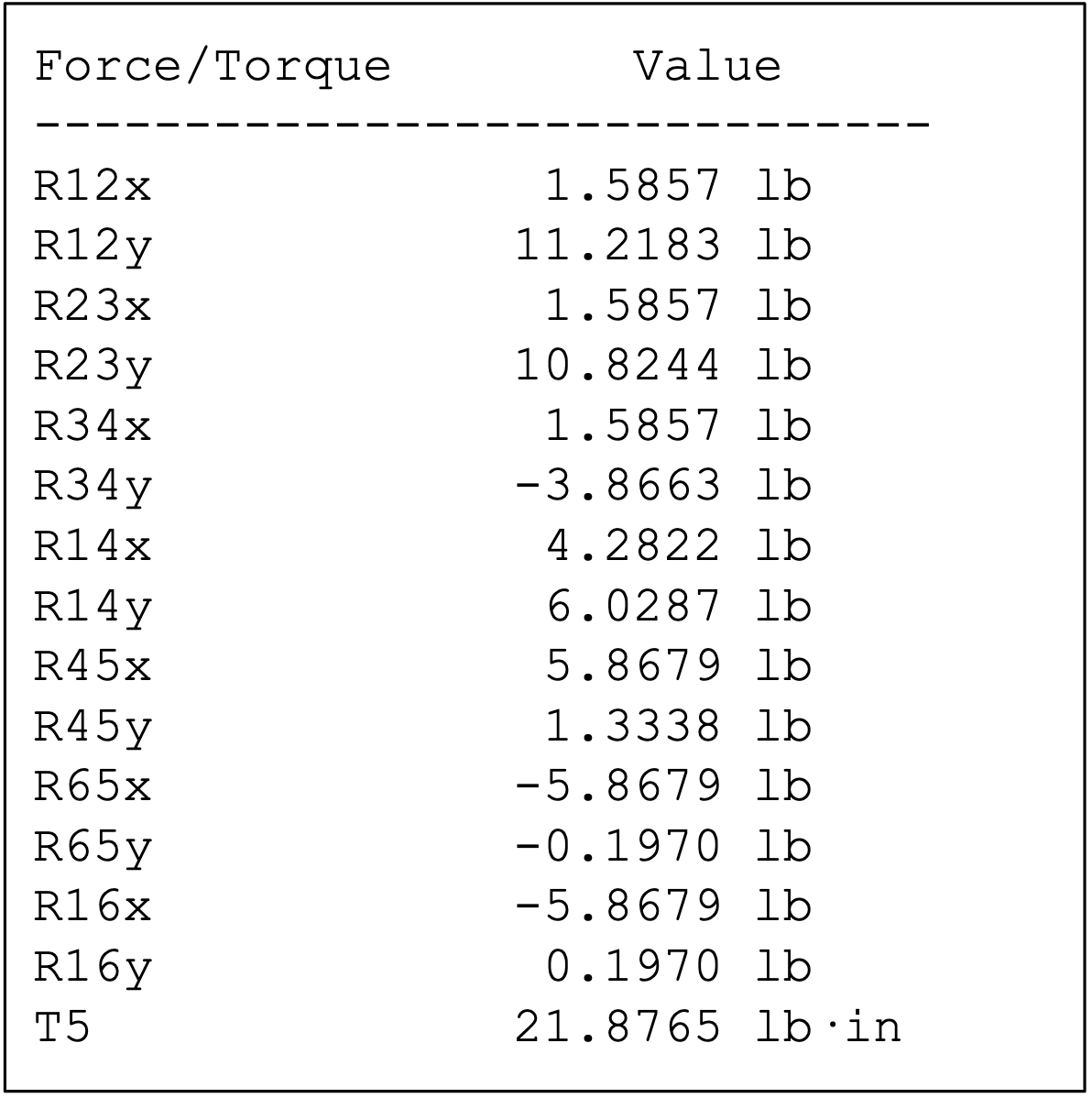
Calculated Force Outputs
Pin force magnitudes at each joint were computed from the static analysis and are shown in the force diagram. These values validated that the plywood links, PLA printed scoop, and off-the-shelf M3/M5 stainless steel hardware were all appropriately sized for the expected prototype loads. The linear guide rail (stainless steel, sourced from Amazon) and 8020 extrusion frame provided more than sufficient structural margin.
Mechanism Animation
Python-animated six-bar mechanism simulation — sweeping through one full crank rotation, showing position, angular velocity, and angular acceleration of all links in real time